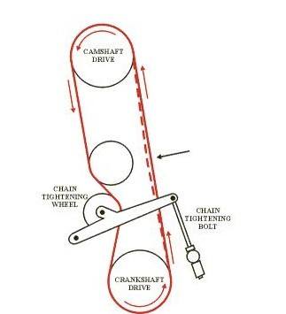
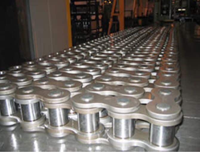
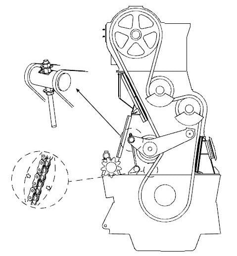
A chain drive is used to transmit motion from the crankshaft of the engine to the camshaft. This drive is known as timing chain and it is responsible for rotation of the camshaft which governs the fuel pump and exhaust valve timings.
Conventional Marine engines comprises of crankshaft and camshaft, whose combine effect produce large amount of power either to drive a propeller or to generate electrical power for ship. A cam shaft unit is used to drive fuel pump and valve unit of the marine engine.
In a 2 stroke engine, the rotational speed of cam shaft is half that of crankshaft rotational speed and in 4 stroke engine it is same as that of crankshaft.
For 2 stroke conventional engines, two methods are used to transmit the crankshaft rotation to cam shaft-
- By timing gear or reduction gear
- By timing chain
In this article we will learn the tightening procedure of timing chain drive which is mainly used in MAN B&W engines.
Following procedures to be followed:
1) Inform company and take permission
2) Take immobilization certificate from the port officials
3) Read the manual and have a toll box meeting with everyone involved in the job. Discuss the procedure
4) Prepare important tools and spares
5) Prepare risk assessment which must include all the personnel involved in the operation
6) Shut starting air for main engine. Paste notice and ply cards
7) Engage turning gear
8) Open indicator cocks
9) After stopping and cooling down of engine for sufficient time, stop main lube oil pump
10) Open crank case doors for forward, aft unit and the door incorporating the chain drive
11) Put blower and ventilate it thoroughly.
12) Prepare enclosed space entry checklist which involves checking of internal atmosphere for oxygen and hydrocarbon gas
13) After sufficient ventilation wearing proper PPE you can enter the Crankcase.
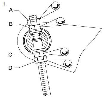
14) Open tab washer for nut A & B and C & D.
15) Loosen the nut A, B, C, D to free the chain tightener bolt.
16) Turn the engine so that the slack side of the chain is on the same side as the tightener wheel.
17) Make sure that the balance weights are hanging downwards.
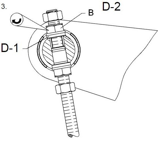
18) Now tighten nut B as it is loose on the chain tightener bolt (keep measuring with feeler gauge) until there is a clearance of 0.1mm between the shaft and the nut.
19) Now tighten nut B as stated in D-2 (Tightening angle – 720 ° = 12 hexagons)
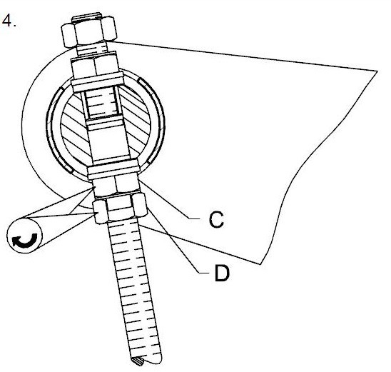
20) Tighten nut C hard against the contact face of the shaft.
21) Tighten nut D and then lock nut C & D with a tab washer.
22) Tighten nut A and lock nut A & B with a tab washer.
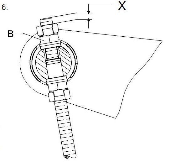
23) Measure distance “X”.
24) If the chain is worn i.e. “X” >165mm repeat the whole tightening procedure. But tighten nut B on a reduced tightening angle i.e. reduced tightening angle – 600 ° = 10 hexagons.
25) If the distance X exceeds the max distance of 265mm find and eliminate the cause of abnormal chain elongation e.g. defective chain, damaged chain wheel or bearing etc.

No comments:
Post a Comment