Showing posts with label man b&w. Show all posts

10/24/2013

The Most Popular Marine Propulsion Engines in the Shipping Industry

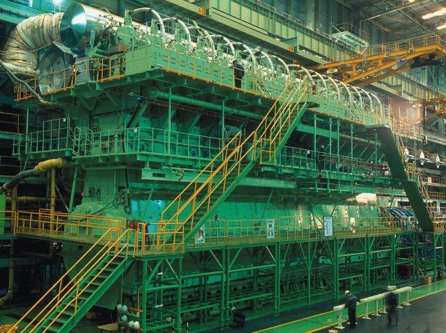
Marine engines are one of the biggest and expensive engines in the world. It requires great engineering skills and resources to manufacture such massive machinery, which is responsible for propulsion of the ship. The criteria for purchasing a marine engine are to get higher speed along with economical fuel consumption and long machinery life.
As more and more stringent environmental regulations are introduced, engine manufacturers are also working on their research and development to comply with stringent emission norms keeping in mind the economical factors for the ship owners or buyers.
There are many engine manufacturer designs that you will see on a vessel, but the most prominent players in the engine manufacturing industry are SULZER, MAN and B&W.
The famous marine engines which were widely used as a ship propulsion plant are as follows:

SULZER
RD series
It is the oldest engine series from SULZER and very rarely seen in shipping industry today.It is equipped with rotary exhaust valves and fuel valve with short spindle. The cylinder liner quills were of wet type and placed only at the upper part. It has pulse turbo charging system with no auxiliary blower fitted for supporting the scavenge pressure.

RND series
One of the most famous design of SULZER with a slogan of “Our Exhaust valves never burns” as this engine doesn’t have any. It has loop scavenging i.e. exhaust and inlet ports are provided in the liner. It was fitted with more liner quills at the bottom of exhaust port and is of dry type. Auxiliary blowers are provided and constant turbo charging system is adopted. It produces more power than the engines of RD series.

RTA series
It is the modern day engine design with exhaust valves fitted. It has become very famous in modern shipping as it is a balanced blend of automation and mechanical engineering. It consumes less fuel and produces more power with three fuel valves in one cylinder.

RT Flex series
It is the latest and the toughest engine from Wartsila Sulzer with maximum automation installed. It consists of a common rail fuel injection method and uses fully integrated electronic system based on a high performance computer eliminating parts like fuel pump, fuel cam, chain drive etc. resulting in reduced maintenance.

MAN B&W
MAN B&W is another leading diesel engine manufacturer with the head office situated in Germany. It has different categories of engines for different users with latest ME-B series complying with the latest norms and taking care of ship owner’s economical criterion of selection.
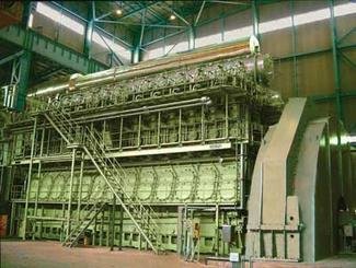
KEF series
It was introduced about 20 years ago and is incorporated with exhaust valves which are push rod operated and installed with pulse type turbo charging system. No servomotor was fitted in this engine and reversing is done with mechanical means.

KGF Series
The KGF series was similar to KEF series and consists of exhaust valve rotator with roller bearing installed for that. In this engine the reversing cam is held in a hub which is keyed in to the shaft. Cam shaft is turned in the same direction for reversing and the pressure required for reversing is about 40 bars. There is no direct link between chain drive and engine cam shaft.

MC series
The MC series engines are the most popular engines now and are fitted with electronic control unit for better and safe operation of the engine. This engine is installed with VIT for an economical fuel consumption and power production. Air is used for reversing of the engine which moves the fuel pump cam follower from ahead to astern position.

ME series
It is the upgraded version of MC engine with electronic automation installed for safety and economy of the plant. They provide optimal combustion at all operations and speed with smokeless operation. This series also comes with liquid gas injection system for LPG fuel.

9/23/2013

Procedure for Removing Main Bearing of MAN B&W MC-C Engine

Efficient maintenance of main engine of the ship ensures smooth running, higher efficiency, and minimum breakdown. Main bearing of the main engine is one such part which can withhold the working of the whole engine if confronted with a fault. In this article we will have a look at the procedure for removal of main bearing of MAN B&W MC-C Engine.
Moreover, the main bearing of a ship’s main engine must be overhauled when its running hours as stated by the engine maker have been completed. Apart from this, if there is any sign of bearing worn out or if the bearing temperature is going high, it is imperative to open the main bearing for inspection.
The procedure for opening of the main bearing is as follows:
1)       Inform company and take permission.
2)       Take immobilization certificate from port state Authority stating that the main engine will not be available for a particular period of time.
3)       Read the manual and have a toll box meeting with everyone involved in the job. Discuss the procedure.
4)       Prepare important tools and spares to be used in operation.
5)       Prepare risk assessment with the personnel involved in operation.
6)       Shut starting air valve for main engine.
7)       Open indicator cocks of all the units.
8)       Engage turning gear and put it in remote control. The remote control switch to be operated by in charge of the operation.
9)       Stop main lube oil pump.
10)    Open crank case doors.
11)    Put blower and ventilate it thoroughly.
12)    Prepare enclosed space entry checklist.
13)    After sufficient ventilation, wearing proper PPE enter the C/C.
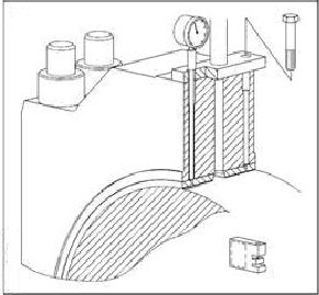
14)    Make sure that the main bearing measuring tool (depth gauge) is calibrate and set to ’0′.
15)    Open the screws of lube oil pipe connection and insert the depth gauge and measure the clearance between upper bearing keep and journal.
16)    Compare this reading with the earlier reading in the record or the new bearing reading.
17)    Now disconnect the lube oil pipe line.
18)    Turn the crank throw so that it is towards the exhaust side.
19)    Now mount the hydraulic jacks and loosen the main bearing stud nuts.
20)    Mount the lifting tool for main bearing keep and lift the keep using a pulley and a wire rope.
21)    Note the marking on the main bearing keep before lifting for correct direction of the keep.
22)    Guide the keep safely outside with a help of another chain block and place it on a wooden base once it is out.
23)    Mount the tool for lifting the upper bearing shell and place it safely outside.
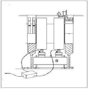
24)    Place the strong back (cross piece) support on the bed plate so that its ends rest on the cross girders.
25)    Mount the hydraulic jack on the cross piece placing it such that it lies beneath the crank webs.
26)    Mount a dial gauge on the adjacent main bearing so that the lift of the crank shaft can be recorded.
27)    Now with hydraulic pressure (1500-1650 bar) lift the crankshaft corresponding to the main bearing clearance to the adjacent main bearing, and check the lift with the help of a dial gauge.
28)    Remove the lock screws from the lower shell.
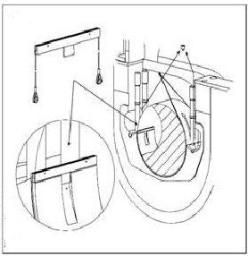
29)    Place the dismantling tool on the lower bearing shell such that the flap enters the oil groove.
30)    Pull the bearing shell round and up so that it lies on the journal and take it out safely.

9/22/2013

Chain Tightening Procedure for MAN B&W Engine

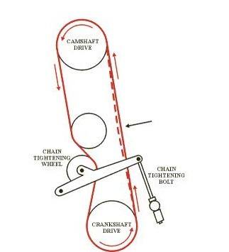
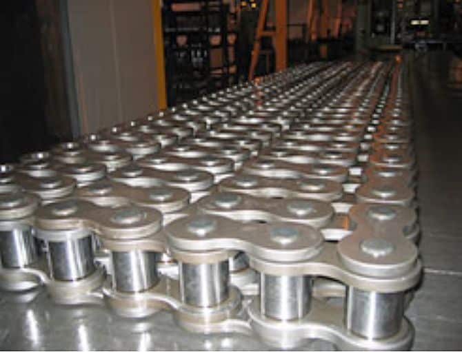
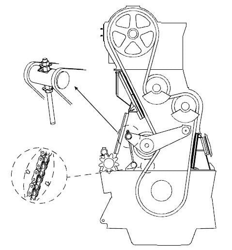
A chain drive is used to transmit motion from the crankshaft of the engine to the camshaft. This drive is known as timing chain and it is responsible for rotation of the camshaft which governs the fuel pump and exhaust valve timings.
Conventional Marine engines comprises of crankshaft and camshaft, whose combine effect produce large amount of power either to drive a propeller or to generate electrical power for ship. A cam shaft unit is used to drive fuel pump and valve unit of the marine engine.
In a 2 stroke engine, the rotational speed of cam shaft is half that of crankshaft rotational speed and in 4 stroke engine it is same as that of crankshaft.
For 2 stroke conventional engines, two methods are used to transmit the crankshaft rotation to cam shaft-
  •  By timing gear or reduction gear
  • By timing chain
In this article we will learn the tightening procedure of timing chain drive which is mainly used in MAN B&W engines.
 Following procedures to be followed:  
1)       Inform company and take permission
2)       Take immobilization certificate from the port officials
3)       Read the manual and have a toll box meeting with everyone involved in the job. Discuss the procedure
4)       Prepare important tools and spares
5)       Prepare risk assessment which must include all the personnel involved in the operation
6)       Shut starting air for main engine. Paste notice and ply cards
7)       Engage turning gear
8)       Open indicator cocks
9)        After stopping and cooling down of engine for sufficient time, stop main lube oil pump
10)    Open crank case doors for forward, aft unit and the door incorporating the chain drive
11)    Put blower and ventilate it thoroughly.
12)    Prepare enclosed space entry checklist which involves checking of internal atmosphere for oxygen and hydrocarbon gas
13)    After sufficient ventilation wearing proper PPE you can enter the Crankcase.
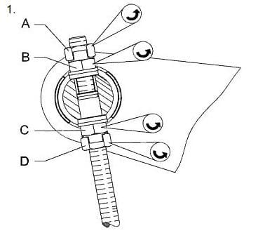
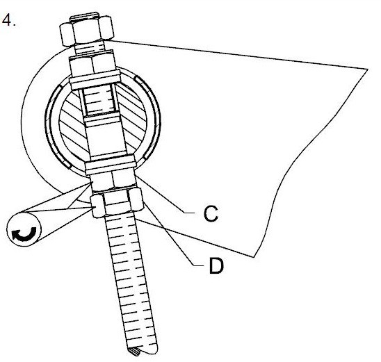
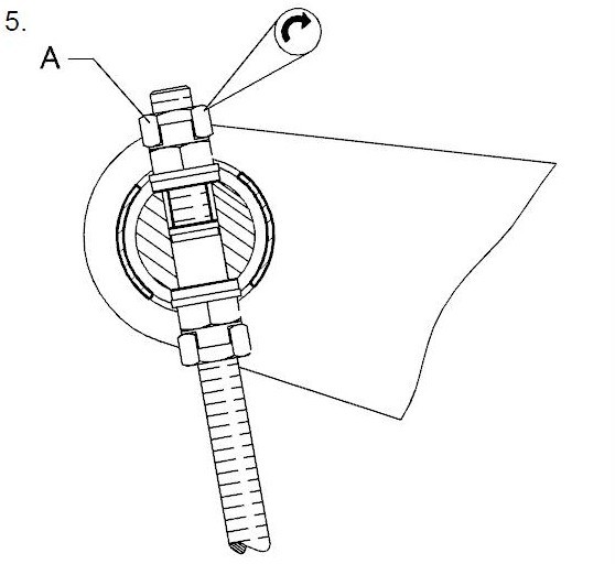
14)    Open tab washer for nut A & B and C & D.
15)    Loosen the nut A, B, C, D to free the chain tightener bolt.
16)    Turn the engine so that the slack side of the chain is on the same side as the tightener wheel.
17)    Make sure that the balance weights are hanging downwards.
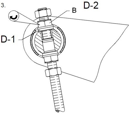
18)    Now tighten nut B as it is loose on the chain tightener bolt (keep measuring with feeler gauge) until there is a clearance of 0.1mm between the shaft and the nut.
19)    Now tighten nut B as stated in D-2 (Tightening angle – 720 ° = 12 hexagons)
20)    Tighten nut C hard against the contact face of the shaft.
21)    Tighten nut D and then lock nut C & D with a tab washer.
22)    Tighten nut A and lock nut A & B with a tab washer.
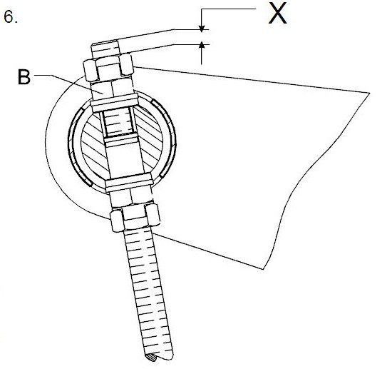
23)       Measure distance “X”.
24)       If the chain is worn i.e. “X” >165mm repeat the whole tightening procedure. But tighten nut B on a reduced tightening angle i.e. reduced tightening angle – 600 ° = 10 hexagons.
25)       If the distance X exceeds the max distance of 265mm find and eliminate the cause of abnormal chain elongation e.g. defective chain, damaged chain wheel or bearing etc.